RP2040 – The Ideal Choice for Solar-Powered Embedded Systems
A technical analysis of why the RP2040 excels in solar-powered and battery-operated applications – wide operating voltage range, ultra-low deep sleep current, and built-in ADC for monitoring.
The Challenge of Solar-Powered Embedded Systems
For engineers and makers venturing into solar power, the choice of microcontroller is critical. It must be powerful enough to perform its tasks, yet frugal enough to run on a trickle of energy harvested from the sun.
A solar-powered system typically consists of:
- Solar panel – Harvests energy from sunlight.
- Battery – Stores energy for use when sunlight is unavailable.
- Charge controller – Manages battery charging.
- Microcontroller – Executes the application logic.
- Sensors/peripherals – Collects data or performs actions.
The microcontroller is the heart of the system. Its power consumption directly determines battery life and overall system viability.
Why the RP2040 Excels in Solar Applications
1. A Wide, Forgiving Operating Voltage Range
One of the most significant challenges in solar-powered designs is the fluctuating voltage from the panel and battery. The RP2040 is exceptionally robust in this regard.
| Feature | RP2040 | Typical 3.3V MCU |
|---|---|---|
| Operating Voltage Range | 1.8V - 3.3V | 2.7V - 3.6V |
| Low-Voltage Operation | ✅ Down to 1.8V | ❌ May brownout below 2.7V |
| Voltage Tolerance | ✅ Wide margin | ❌ Narrow margin |
Benefits for Solar:
- Deep Discharge Operation: The ability to function down to 1.8V means your device can continue operating even as a battery is deeply discharged, extracting every last bit of stored energy.
- Resilience to Fluctuations: Unlike many 3.3V-only microcontrollers that can be damaged by voltages slightly above their limit, the RP2040 can tolerate a wider band, making it more resilient to the unpredictable output of a solar panel.
- Simpler Power Design: The wide range reduces the need for precise voltage regulation, allowing for simpler, more efficient power supply designs.
2. Extremely Low Power Consumption for Autonomous Operation
For a solar-powered device, the power consumed while “sleeping” is just as important as its active power. The RP2040 excels in this area.
| Power Mode | RP2040 | Typical 32-bit MCU |
|---|---|---|
| Active (133MHz) | ~20-30mA | ~10-50mA |
| Deep Sleep | ~180µA | ~1-5mA |
| Dormant (Lowest) | < 2µA | Not applicable |
Benefits for Solar:
- Extended Battery Life: A device that spends 99% of its time in deep sleep (180µA) can run for months or even years on a small battery.
- Efficient Duty Cycling: By combining a powerful ARM Cortex-M0+ core with ultra-low sleep modes, the RP2040 can follow the “sleep, wake, process, sleep” pattern of a typical IoT sensor node very efficiently.
- Energy Harvesting Viability: The low sleep current makes it feasible to power the device entirely from harvested energy, eliminating the need for battery replacement.
3. Built-In ADC for Monitoring
The RP2040 includes a 4-channel 12-bit Analog-to-Digital Converter (ADC). This is critical for solar projects, allowing you to monitor the voltage of your solar panel and battery directly.
- Simple Monitoring: Use a voltage divider to scale down the panel’s voltage to the 0-3.3V range of the ADC.
- Intelligent Decision Making: The RP2040 can make decisions based on battery voltage – only performing tasks when the battery is sufficiently charged, or logging system performance over time.
- Early Warning: Detect low battery conditions before the system shuts down, allowing for graceful operation or data saving.
RP2040 vs. The Competition
How does the RP2040 stack up against other common choices for solar projects?
| Feature | RP2040 | ESP32 | ATmega328P (Arduino Uno) |
|---|---|---|---|
| Core | Dual-core ARM Cortex-M0+ | Dual-core Xtensa LX6 | 8-bit AVR |
| Clock Speed | 133MHz | 240MHz | 16MHz |
| Deep Sleep Current | ~180µA | ~10µA (ULP) | ~1-5µA (Power Down) |
| Operating Voltage | 1.8V - 3.3V | 2.2V - 3.6V | 1.8V - 5.5V |
| Built-in Wireless | No | Yes (Wi-Fi/BT) | No |
| ADC Resolution | 12-bit | 12-bit | 10-bit |
| RAM | 264KB | 520KB | 2KB |
| Cost | ~$4-5 | ~$6-10 | ~$2-3 |
Analysis
| MCU | Pros for Solar | Cons for Solar |
|---|---|---|
| RP2040 | ✅ Wide voltage range (1.8-3.3V). ✅ Very low deep sleep current. ✅ Good ADC resolution. ✅ Large RAM for data buffering. | ⚠️ No built-in wireless (requires external module). |
| ESP32 | ✅ Very low deep sleep current (10µA). ✅ Built-in Wi-Fi/BT. ✅ Powerful processing. | ❌ Narrow voltage range (2.2-3.6V). ❌ High active current (~40-80mA with Wi-Fi). |
| ATmega328P | ✅ Extremely low power down current (1-5µA). ✅ Wide voltage range (1.8-5.5V). ✅ Very low cost. | ❌ Low processing power. ❌ Limited memory (2KB RAM). ❌ 10-bit ADC only. |
Conclusion: The RP2040 offers the best balance of power, voltage flexibility, and features for solar-powered applications that don’t require built-in wireless connectivity. Its combination of a wide operating voltage range and very low deep sleep current makes it an ideal choice for battery-operated and energy-harvesting projects.
Simple Autonomous Example: Solar-Powered Temperature Logger
This example demonstrates a basic, self-contained temperature logger that can be powered by a small solar panel and a battery.
Concept
- Wake Up: After a long sleep (e.g., 60 seconds), the RP2040 powers up.
- Read Sensor: It reads a temperature sensor (analog thermistor or DS18B20).
- Log Data: It stores the reading or transmits it (via serial, LoRa, etc.).
- Return to Sleep: It goes back into deep sleep to conserve power.
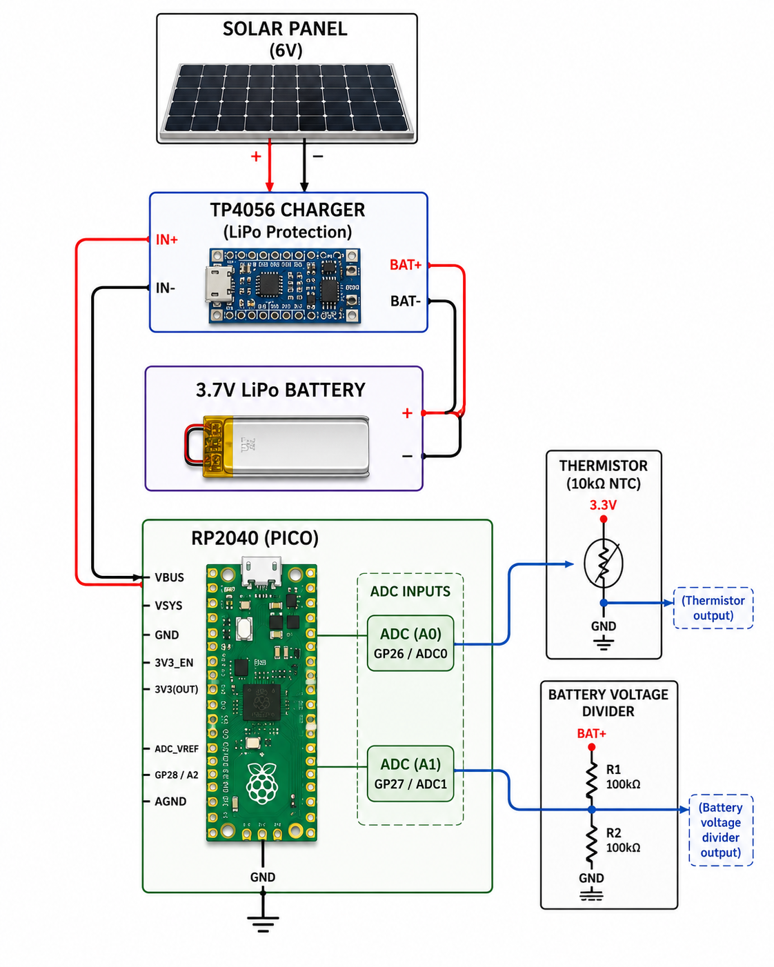
Components Needed
| Component | Purpose |
|---|---|
| RP2040 board | Raspberry Pi Pico (or any RP2040 board). |
| Temperature sensor | Analog thermistor (or DS18B20). |
| Solar panel | 6V small panel (e.g., 1-2W). |
| LiPo battery | 3.7V 500mAh (or larger). |
| TP4056 | LiPo charging module with protection. |
| Voltage divider | Two resistors (e.g., 10kΩ and 10kΩ) for battery monitoring. |
Circuit Diagram
Code (Arduino IDE with arduino-pico core)
This code uses the arduino-pico core and its LowPower library to implement deep sleep.
#include <Arduino.h>
#include <LowPower.h>

// ─── Pin Definitions ─────────────────────────────────────────────
#define TEMP_SENSOR_PIN A0   // Analog input for thermistor
#define BATTERY_PIN A1       // Analog input for battery divider

// ─── Sleep Duration ──────────────────────────────────────────────
const unsigned long SLEEP_TIME_MS = 60000;  // Sleep for 60 seconds

// ─── Thermistor Parameters ──────────────────────────────────────
// These values depend on your specific thermistor
const float THERMISTOR_NOMINAL = 10000.0;   // 10kΩ at 25°C
const float TEMPERATURE_NOMINAL = 25.0;     // 25°C
const float B_COEFFICIENT = 3950.0;         // B value (typical for 10k thermistor)
const float SERIES_RESISTOR = 10000.0;      // 10kΩ series resistor

// ─── Functions ──────────────────────────────────────────────────

float readTemperature() {
    int raw = analogRead(TEMP_SENSOR_PIN);
    float voltage = raw * (3.3 / 1023.0);

    // Calculate thermistor resistance
    float resistance = SERIES_RESISTOR * (3.3 / voltage - 1.0);

    // Steinhart-Hart equation
    float steinhart = 1.0 / TEMPERATURE_NOMINAL +
                      (1.0 / B_COEFFICIENT) * log(resistance / THERMISTOR_NOMINAL);
    float temperatureC = (1.0 / steinhart) - 273.15;

    return temperatureC;
}

float readBatteryVoltage() {
    int raw = analogRead(BATTERY_PIN);
    float voltage = raw * (3.3 / 1023.0);

    // Multiply by divider ratio (assuming 1:1 divider)
    return voltage * 2.0;
}

// ─── Main Code ──────────────────────────────────────────────────

void setup() {
    Serial.begin(115200);
    delay(100);
    Serial.println("\n🌞 Solar-Powered Temperature Logger");
    Serial.println("========================================");
}

void loop() {
    // 1. Read Temperature
    float temperature = readTemperature();

    // 2. Read Battery Voltage
    float batteryVoltage = readBatteryVoltage();

    // 3. Log Data
    Serial.print("🌡️ Temperature: ");
    Serial.print(temperature);
    Serial.print(" °C | ");
    Serial.print("🔋 Battery: ");
    Serial.print(batteryVoltage);
    Serial.println(" V");

    // 4. Check battery condition
    if (batteryVoltage < 3.3) {
        Serial.println("⚠️ Low battery! Consider reducing sleep interval.");
    }

    // 5. Enter Deep Sleep
    Serial.print("💤 Going to sleep for ");
    Serial.print(SLEEP_TIME_MS / 1000);
    Serial.println(" seconds...");
    Serial.println();

    delay(100);  // Allow serial to finish

    // Enter deep sleep for the specified duration
    LowPower.deepSleep(SLEEP_TIME_MS);

    // ─── Execution resumes here after wake ─────────────────────
    Serial.println("⏰ Woke up from sleep!");
}
How It Works
| Step | Action |
|---|---|
| 1. Wake | The RP2040 wakes from deep sleep after 60 seconds (or on power-up). |
| 2. Read | The code reads the thermistor and calculates temperature. It also reads battery voltage via a voltage divider. |
| 3. Log | Data is printed to the serial monitor (this could be replaced with SD card logging or LoRa transmission). |
| 4. Sleep | LowPower.deepSleep(SLEEP_TIME_MS) puts the RP2040 into deep sleep. The internal RTC timer wakes it up after 60 seconds. |
Power Consumption:
- Active (2ms): ~20mA for a few milliseconds.
- Deep Sleep (59.998s): ~180µA for the rest of the time.
Battery Life Estimate (500mAh LiPo):
| Duty Cycle | Calculation | Estimated Life |
|---|---|---|
| Active | 2ms @ 20mA = 0.04mAh per cycle | – |
| Sleep | 60s @ 180µA = 3µAh per cycle | – |
| Total per Cycle | 3.04µAh | – |
| Cycles per Day | 1440 | – |
| Daily Consumption | 4.38mAh | – |
| Battery Life | 500mAh ÷ 4.38mAh/day | ~114 days (almost 4 months) |
Power Optimization Tips
| Tip | Description |
|---|---|
| ✅ Use the 3.3V rail | Power the RP2040 directly from the battery via a 3.3V regulator (or use a 3.3V LiPo). |
| ✅ Turn off peripherals | Disable I2C, SPI, and UART before entering sleep. |
| ✅ Use external pull-ups | Internal pull-ups consume ~50µA per pin; use external 10kΩ resistors instead. |
| ✅ Monitor battery voltage | Use the ADC to avoid deep discharge. |
| ✅ Reduce clock speed | Run at 48MHz or lower to reduce active current. |
| ✅ Disable USB | The USB peripheral draws ~2mA; disable it before sleep. |
| ✅ Use sleep longer | Increase sleep interval to reduce average power. |
Key Takeaways
| Concept | Why It Matters for Solar |
|---|---|
| Wide voltage range (1.8-3.3V) | Operates even when battery voltage drops low. |
| Deep sleep current (~180µA) | Enables months of operation on a small battery. |
| Built-in ADC | Monitor battery voltage and panel output. |
| Dual-core capability | Process data while handling wireless tasks. |
| Low cost (~$4-5) | Economical for large deployments. |
| Large RAM (264KB) | Buffer data when offline. |
Conclusion
The RP2040 is a standout choice for solar-powered and battery-operated embedded systems. Its ability to operate from 1.8V to 3.3V provides exceptional flexibility and resilience to voltage fluctuations from solar panels and batteries. Its ultra-low deep sleep current of ~180µA makes it incredibly efficient for autonomous, duty-cycled operation, ideal for remote sensors that wake up, take a measurement, and go back to sleep.
Combined with its built-in ADC for monitoring the power source, the RP2040 provides a powerful, yet frugal foundation for your next green energy project.
This analysis is part of my broader Embedded Systems Engineering practice. For a detailed technical walkthrough or custom battery-powered design, feel free to reach out.