Embedded Systems – Banana Pi BPI-M2 Ultra GPIO Control
Complete GPIO control guide for the Banana Pi BPI-M2 Ultra – Allwinner A40i, 2GB RAM, 8GB eMMC. Working with Raspberry Pi images, WiringPi, and GPIO control for LEDs, sensors, and automation.
Overview
The Banana Pi BPI-M2 Ultra is a powerful single-board computer based on the Allwinner A40i SoC, featuring:
- Allwinner A40i – Quad-core ARM Cortex-A7.
- 2GB DDR3 RAM – Ample memory for embedded applications.
- 8GB eMMC – On-board storage.
- On-board Wi-Fi & Bluetooth – Built-in wireless connectivity.
- Raspberry Pi compatible – 40-pin GPIO header with Raspberry Pi pinout.
This page documents my experience getting the Banana Pi BPI-M2 Ultra running with GPIO control, including the critical steps to choose the right OS image and configure the GPIO pins.
Architecture
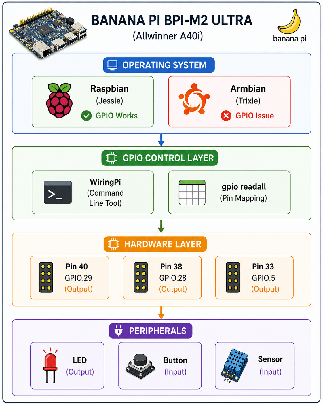
Getting Started
Hardware Specifications
| Component | Specification |
|---|---|
| SoC | Allwinner A40i (Quad-core ARM Cortex-A7) |
| RAM | 2GB DDR3 |
| Storage | 8GB eMMC + microSD card slot |
| Networking | On-board Wi-Fi + Bluetooth |
| GPIO | 40-pin header (Raspberry Pi compatible) |
| Power | 5V DC (quality power supply essential) |
⚠️ Critical: Power Supply Quality
Quality power is essential. The Banana Pi is sensitive to power fluctuations. Use a reliable power supply (I used a laptop adapter). Poor power can cause:
- Random crashes and reboots.
- GPIO instability.
- USB device detection issues.
OS Image Selection: Working vs Non-Working
✅ Working Image (GPIO Works)
Image: 2017-08-24-raspbian-jessie-beta-bpi-m2u-sd-emmc.img.zip
- OS: Raspbian Jessie (Raspberry Pi OS).
- GPIO: Fully working with WiringPi.
- Source: Google Drive (Banana Pi official).
Download: Banana Pi Google Drive
❌ Non-Working Image (GPIO Does Not Work)
Image: Armbian-unofficial_26.02.0-trunk_Bananapim2ultra_trixie_current_6.12.68_xfce_desktop.img.xz
- OS: Armbian Trixie (current).
- GPIO: No GPIO effect (WiringPi not compatible or missing drivers).
- Issue: The newer kernel does not support the GPIO interface correctly.
Recommendation
Use the older Raspbian Jessie image for reliable GPIO control. The newer Armbian images may offer more modern features, but GPIO is broken.
GPIO Pin Mapping
gpio readall Output
root@bpi-iot-ros-ai:/home/pi# gpio readall
 +-----+-----+---------+------+---+---Pi ?---+---+------+---------+-----+-----+
 | BCM | wPi |   Name  | Mode | V | Physical | V | Mode | Name    | wPi | BCM |
 +-----+-----+---------+------+---+----++----+---+------+---------+-----+-----+
 |     |     |    3.3v |      |   |  1 || 2  |   |      | 5v      |     |     |
 |  53 |   8 |   SDA.1 | ALT5 | 0 |  3 || 4  |   |      | 5v      |     |     |
 |  52 |   9 |   SCL.1 | ALT5 | 0 |  5 || 6  |   |      | 0v      |     |     |
 |  35 |   7 | GPIO. 7 | ALT3 | 0 |  7 || 8  | 0 | ALT4 | TxD     | 15  | 274 |
 |     |     |      0v |      |   |  9 || 10 | 0 | ALT4 | RxD     | 16  | 275 |
 | 276 |   0 | GPIO. 0 | ALT3 | 0 | 11 || 12 | 0 | ALT3 | GPIO. 1 | 1   | 273 |
 | 277 |   2 | GPIO. 2 | ALT3 | 0 | 13 || 14 |   |      | 0v      |     |     |
 | 249 |   3 | GPIO. 3 | ALT2 | 0 | 15 || 16 | 0 | ALT3 | GPIO. 4 | 4   | 272 |
 |     |     |    3.3v |      |   | 17 || 18 | 0 | ALT2 | GPIO. 5 | 5   | 250 |
 |  64 |  12 |    MOSI | ALT4 | 0 | 19 || 20 |   |      | 0v      |     |     |
 |  65 |  13 |    MISO | ALT4 | 0 | 21 || 22 | 0 | ALT2 | GPIO. 6 | 6   | 251 |
 |  66 |  14 |    SCLK | ALT4 | 0 | 23 || 24 | 0 | ALT4 | CE0     | 10  | 87  |
 |     |     |      0v |      |   | 25 || 26 | 0 | ALT2 | CE1     | 11  | 248 |
 | 257 |  30 |   SDA.0 | ALT3 | 0 | 27 || 28 | 0 | ALT3 | SCL.0   | 31  | 256 |
 | 224 |  21 | GPIO.21 | ALT4 | 0 | 29 || 30 |   |      | 0v      |     |     |
 | 225 |  22 | GPIO.22 | ALT4 | 0 | 31 || 32 | 0 | ALT3 | GPIO.26 | 26  | 116 |
 | 226 |  23 | GPIO.23 | ALT4 | 0 | 33 || 34 |   |      | 0v      |     |     |
 | 227 |  24 | GPIO.24 | ALT4 | 0 | 35 || 36 | 0 | ALT4 | GPIO.27 | 27  | 231 |
 | 228 |  25 | GPIO.25 | ALT4 | 0 | 37 || 38 | 0 | ALT4 | GPIO.28 | 28  | 230 |
 |     |     |      0v |      |   | 39 || 40 | 0 | ALT4 | GPIO.29 | 29  | 229 |
 +-----+-----+---------+------+---+----++----+---+------+---------+-----+-----+
 | BCM | wPi |   Name  | Mode | V | Physical | V | Mode | Name    | wPi | BCM |
 +-----+-----+---------+------+---+---Pi ?---+---+------+---------+-----+-----+
Key Pins for GPIO Control
| Physical Pin | wPi | BCM | Name | Current Mode | Status |
|---|---|---|---|---|---|
| 40 | 29 | 229 | GPIO.29 | ALT4 | ⚠️ Needs mode change |
| 38 | 28 | 230 | GPIO.28 | ALT4 | ⚠️ Needs mode change |
| 36 | 27 | 231 | GPIO.27 | ALT4 | ⚠️ Needs mode change |
| 33 | 23 | 226 | GPIO.23 | ALT4 | ⚠️ Needs mode change |
| 35 | 24 | 227 | GPIO.24 | ALT4 | ⚠️ Needs mode change |
| 37 | 25 | 228 | GPIO.25 | ALT4 | ⚠️ Needs mode change |
Important: Many GPIOs are in ALT4 (alternative function) by default. They must be switched to OUTPUT mode before use.
Controlling GPIO.29 (Pin 40)
Pin 40 is a useful GPIO pin (GPIO.29, wPi 29, BCM 229). However, it is in ALT4 mode by default.
Step 1: Change Mode to OUTPUT
# Set pin 29 to output mode
gpio mode 29 out

# Verify the change
gpio readall
Now Pin 40 should show OUT in the Mode column.
Step 2: Write Values
# Set HIGH (1)
gpio write 29 1

# Set LOW (0)
gpio write 29 0
Step 3: Blink an LED
Connect an LED with a 330Ω resistor between Pin 40 and GND (Pin 39), then run:
# Blink the LED
while true; do
    gpio write 29 1
    sleep 0.5
    gpio write 29 0
    sleep 0.5
done
Example Projects
1. 🚦 LED Blinker (Hardware Test)
Hardware: LED + 330Ω resistor between Pin 40 and GND.
# Simple blink using gpio command
while true; do
    gpio write 29 1
    sleep 0.5
    gpio write 29 0
    sleep 0.5
done
2. 🎮 Button Input
Hardware: Push button between Pin 40 and GND.
# Read button state
while true; do
    state=$(gpio read 29)
    if [ $state -eq 0 ]; then
        echo "Button pressed!"
    else
        echo "Button released"
    fi
    sleep 0.1
done
3. 🐍 Python GPIO Control
#!/usr/bin/env python3
import time
import wiringpi

# Initialize WiringPi
wiringpi.wiringPiSetup()

# Set pin 29 (wPi) as output
wiringpi.pinMode(29, 1)  # 1 = OUTPUT

try:
    while True:
        wiringpi.digitalWrite(29, 1)  # HIGH
        print("LED ON")
        time.sleep(0.5)
        wiringpi.digitalWrite(29, 0)  # LOW
        print("LED OFF")
        time.sleep(0.5)
except KeyboardInterrupt:
    wiringpi.digitalWrite(29, 0)
    print("\nExited")
4. 🌡️ DHT11 Sensor
# Install DHT library
sudo apt update
sudo apt install python3-pip
sudo pip3 install Adafruit_DHT
#!/usr/bin/env python3
import Adafruit_DHT
import time
sensor = Adafruit_DHT.DHT11
pin = 29 # wPi pin number
while True:
humidity, temperature = Adafruit_DHT.read_retry(sensor, pin)
if humidity is not None and temperature is not None:
print(f"Temp: {temperature:0.1f}°C Humidity: {humidity:0.1f}%")
else:
print("Sensor error")
time.sleep(2)Troubleshooting
Issue: GPIO Not Responding
Symptom: gpio write commands have no effect.
Cause:
- Pin is in ALT mode (e.g., ALT4) and not configured as GPIO.
- Using a non-working OS image (Armbian).
Solution:
# Check current mode
gpio readall

# Change to output mode
gpio mode <wPi_pin> out
Issue: gpio Command Not Found
# Install WiringPi
sudo apt update
sudo apt install wiringpi

# Or compile from source
git clone https://github.com/WiringPi/WiringPi.git
cd WiringPi
./build
Issue: Power Supply Problems
Symptom: Random reboots, USB devices not detected, GPIO unstable.
Solution: Use a quality 5V power supply with at least 2A capacity. Avoid phone chargers or cheap USB adapters.
GPIO Reference Table
| Physical Pin | wPi | BCM | Name | Recommended Use |
|---|---|---|---|---|
| 40 | 29 | 229 | GPIO.29 | ✅ General purpose |
| 38 | 28 | 230 | GPIO.28 | ✅ General purpose |
| 36 | 27 | 231 | GPIO.27 | ✅ General purpose |
| 33 | 23 | 226 | GPIO.23 | ✅ General purpose |
| 35 | 24 | 227 | GPIO.24 | ✅ General purpose |
| 37 | 25 | 228 | GPIO.25 | ✅ General purpose |
| 32 | 26 | 116 | GPIO.26 | ✅ General purpose |
| 31 | 22 | 225 | GPIO.22 | ✅ General purpose |
Key Achievements
- Identified working OS image for Banana Pi BPI-M2 Ultra.
- Documented GPIO pin mapping using
gpio readall. - Successfully controlled GPIO.29 (Pin 40) with WiringPi.
- Created reusable scripts for LED, button, and DHT11.
- Solved common issues with power supply and GPIO mode.
Technology Stack
| Category | Technology |
|---|---|
| Board | Banana Pi BPI-M2 Ultra |
| SoC | Allwinner A40i |
| OS | Raspbian Jessie (Working) |
| GPIO Control | WiringPi, gpio commands |
| Language | Python 3, Bash |
| Sensors | DHT11 |
| Peripherals | LED, Button |
Related Projects
- Embedded Systems Engineering – Main embedded systems page.
- aml-s905x-cc-v2 GPIO Control – Similar GPIO exploration.
- Orange Pi One Automation Platform – ARM-based automation.
This Banana Pi GPIO exploration is part of my broader Embedded Systems Engineering practice. For a detailed technical walkthrough or custom automation design, feel free to reach out.