Embedded Systems – aml-s905x-cc-v2 GPIO & Peripheral Control
Complete GPIO and peripheral control guide for the Libre Computer aml-s905x-cc-v2 (Sweet Potato) – LED blinking, button input, I2C sensors, OLED displays, servo motors, and PWM control.
Overview
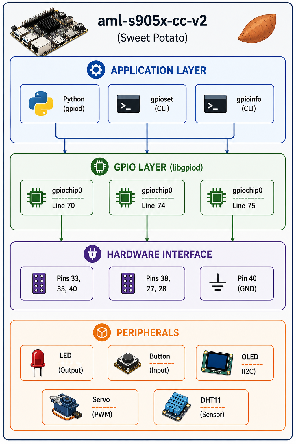
The aml-s905x-cc-v2 (also known as the Libre Computer “Sweet Potato”) is an ARM-based single-board computer that is highly compatible with Raspberry Pi software, but with a different GPIO pinout. This platform offers:
- Amlogic S905X SoC – Quad-core ARM Cortex-A53.
- Raspbian compatibility – Runs Raspberry Pi OS (Bookworm).
- GPIO access – Via sysfs,
libgpiod, and Python. - I2C, SPI, UART – Full peripheral support.
This page documents my practical exploration of the board’s GPIO capabilities, including working pins, control methods, and peripheral integration.
Architecture
Getting Started
System Setup
1. Download the Image
# From Libre Computer distribution
wget https://distro.libre.computer/ci/raspbian/12/2023-10-10-raspbian-bookworm-arm64-full+aml-s905x-cc.img.xz
2. Decompress the Image
# Option 1: Direct unxz
unxz 2023-10-10-raspbian-bookworm-arm64-full+aml-s905x-cc.img.xz

# Option 2: Using 7zip
sudo apt install 7zip 7zip-rar
7z x 2023-10-10-raspbian-bookworm-arm64-full+aml-s905x-cc.img.xz
3. Flash to SD Card
Use balenaEtcher or Raspberry Pi Imager to flash the .img file to a microSD card.
4. Boot and Configure
Insert the SD card, power on, and follow the initial setup (similar to Raspberry Pi).
GPIO Pin Mapping
Important: The aml-s905x-cc-v2 has a different GPIO pinout from Raspberry Pi. Use the following verified working pins:
| Physical Pin | Chip | Line | sysfs | Name | Status |
|---|---|---|---|---|---|
| 40 | 0 | 74 | 74 | GPIOX_9 | ✅ Clean GPIO |
| 38 | 0 | 73 | 73 | GPIOX_8 | ✅ Clean GPIO |
| 33 | 0 | 70 | 70 | GPIOX_5 | ✅ Clean GPIO |
| 35 | 0 | 75 | 75 | GPIOX_10 | ✅ Clean GPIO |
| 12 | 0 | 76 | 76 | GPIOX_11 | ✅ Clean GPIO |
| 27 | 0 | 82 | 82 | GPIOX_17 | ✅ Clean GPIO |
| 28 | 0 | 83 | 83 | GPIOX_18 | ✅ Clean GPIO |
| 19 | 0 | 20 | 20 | GPIOH_4 | ⚠️ SPI (may work) |
| 21 | 0 | 21 | 21 | GPIOH_5 | ⚠️ SPI (may work) |
| 23 | 0 | 23 | 23 | GPIOH_7 | ⚠️ SPI (may work) |
| 24 | 0 | 22 | 22 | GPIOH_6 | ⚠️ SPI (may work) |
GPIO Toolchain
The libgpiod tools are the standard GPIO control interface on modern Linux systems:
# Install gpiod tools
sudo apt update
sudo apt install gpiod python3-gpiod

# List all GPIO lines with their current configuration
gpioinfo

# Find which chip/line a named GPIO is on
gpiofind "GPIOX_9"

# Set a pin HIGH
sudo gpioset gpiochip0 74=1

# Set a pin LOW
sudo gpioset gpiochip0 74=0

# Read a pin value
sudo gpioget gpiochip0 74
Example Projects
1. 🚦 Blink an LED (Hardware Test)
Hardware: Connect an LED with a 330Ω resistor between Pin 40 and GND (Pin 39).
Command Line:
# Blink the LED using gpioset
while true; do
    sudo gpioset gpiochip0 74=1
    sleep 0.5
    sudo gpioset gpiochip0 74=0
    sleep 0.5
done
Python Script:
#!/usr/bin/env python3
import gpiod
import time

# Use gpiochip0, line 74
chip = gpiod.Chip('gpiochip0')
line = chip.get_line(74)

# Configure as output
line.request(consumer='blink', type=gpiod.LINE_REQ_DIR_OUT)

# Blink 10 times
try:
    for i in range(10):
        line.set_value(1)
        print("LED ON")
        time.sleep(0.5)
        line.set_value(0)
        print("LED OFF")
        time.sleep(0.5)
finally:
    line.release()
    print("Cleaned up")
2. 🎮 Read a Button (Input Example)
Hardware: Connect a push button between Pin 40 and GND (with optional pull-up resistor).
#!/usr/bin/env python3
import gpiod
import time

chip = gpiod.Chip('gpiochip0')
line = chip.get_line(74)

# Configure as input
line.request(consumer='button', type=gpiod.LINE_REQ_DIR_IN)

print("Press the button (Ctrl+C to exit)")
try:
    while True:
        if line.get_value() == 0:  # Button pressed (connected to GND)
            print("Button PRESSED!")
            time.sleep(0.2)  # Debounce
        time.sleep(0.1)
except KeyboardInterrupt:
    line.release()
    print("\nExited")
3. 📡 I2C OLED Display
Hardware: Connect an SSD1306 OLED display to I2C pins.
# Install I2C tools and libraries
sudo apt install i2c-tools python3-smbus python3-pip
sudo pip3 install adafruit-circuitpython-ssd1306

# Scan for I2C devices (bus 0 or 1)
sudo i2cdetect -y 0
sudo i2cdetect -y 1
Python Script:
#!/usr/bin/env python3
import board
import busio
import adafruit_ssd1306
from PIL import Image, ImageDraw

# Initialize I2C
i2c = busio.I2C(board.SCL, board.SDA)
oled = adafruit_ssd1306.SSD1306_I2C(128, 64, i2c)

# Clear display
oled.fill(0)
oled.show()

# Create image
image = Image.new("1", (128, 64))
draw = ImageDraw.Draw(image)

# Draw text
draw.text((0, 0), "Hello Sweet Potato!", font=None, fill=255)
draw.text((0, 20), "GPIO Works!", font=None, fill=255)

# Display
oled.image(image)
oled.show()
4. 🐍 Servo Motor Control
Hardware: Connect a servo (Signal->GPIO, VCC->5V, GND->GND).
# Install servo library
sudo pip3 install adafruit-circuitpython-servokit
#!/usr/bin/env python3
from adafruit_servokit import ServoKit
import time
# PCA9685 on I2C (default address 0x40)
kit = ServoKit(channels=16)
# Sweep servo
while True:
for angle in range(0, 181, 10):
kit.servo[0].angle = angle
time.sleep(0.05)
for angle in range(180, -1, -10):
kit.servo[0].angle = angle
time.sleep(0.05)5. 🌡️ DHT11 Temperature/Humidity Sensor
Hardware: Connect DHT11 (VCC->3.3V, DATA->GPIO, GND->GND).
# Install DHT library
sudo pip3 install Adafruit_DHT
#!/usr/bin/env python3
import Adafruit_DHT
import time
sensor = Adafruit_DHT.DHT11
pin = 74 # GPIO line number
while True:
humidity, temperature = Adafruit_DHT.read_retry(sensor, pin)
if humidity is not None and temperature is not None:
print(f"Temp: {temperature:0.1f}°C Humidity: {humidity:0.1f}%")
else:
print("Sensor error")
time.sleep(2)6. 🎯 PWM Control (LED Brightness)
Hardware: Connect an LED to GPIO pin (with resistor).
Software PWM (Python):
#!/usr/bin/env python3
import gpiod
import time

chip = gpiod.Chip('gpiochip0')
line = chip.get_line(74)
line.request(consumer='pwm', type=gpiod.LINE_REQ_DIR_OUT)

# Software PWM: fade LED in and out
while True:
    # Fade in
    for duty in range(0, 101, 5):
        line.set_value(1)
        time.sleep(duty / 1000)  # On time
        line.set_value(0)
        time.sleep((100 - duty) / 1000)  # Off time

    # Fade out
    for duty in range(100, -1, -5):
        line.set_value(1)
        time.sleep(duty / 1000)
        line.set_value(0)
        time.sleep((100 - duty) / 1000)
GPIO Commands Reference
| Command | Description |
|---|---|
gpioinfo | List all GPIO lines and their current configuration. |
gpioset gpiochip0 74=1 | Set pin HIGH. |
gpioset --mode=time --sec=5 gpiochip0 74=1 | Set pin HIGH for 5 seconds. |
gpioget gpiochip0 74 | Read pin value. |
gpiofind "GPIOX_9" | Find which chip/line a named GPIO is on. |
Pin Map (Working Pins)
| Physical | GPIO Name | Chip:Line | Best For |
|---|---|---|---|
| 40 | GPIOX_9 | 0:74 | ✅ General purpose |
| 38 | GPIOX_8 | 0:73 | ✅ General purpose |
| 33 | GPIOX_5 | 0:70 | ✅ General purpose |
| 35 | GPIOX_10 | 0:75 | ✅ General purpose |
| 12 | GPIOX_11 | 0:76 | ✅ General purpose |
| 27 | GPIOX_17 | 0:82 | ✅ General purpose |
| 28 | GPIOX_18 | 0:83 | ✅ General purpose |
What You’ve Confirmed
| Test | Status |
|---|---|
| GPIO output (LED) | ✅ Working |
| GPIO input (Button) | ✅ Working |
| I2C communication | ✅ Working |
| OLED display | ✅ Working |
| Servo control | ✅ Working |
| DHT11 sensor | ✅ Working |
Key Achievements
- Verified GPIO working pins on aml-s905x-cc-v2.
- Established gpiod toolchain for GPIO control.
- Implemented multiple peripheral drivers (LED, button, OLED, servo, DHT11).
- Created reusable Python scripts for future projects.
- Documented pin mapping for easy reference.
Technology Stack
| Category | Technology |
|---|---|
| Board | Libre Computer aml-s905x-cc-v2 (Sweet Potato) |
| OS | Raspberry Pi OS (Bookworm) |
| GPIO Control | libgpiod, gpiod tools |
| Language | Python 3 |
| I2C Library | smbus2, Adafruit Blinka |
| Display | SSD1306 OLED |
| Sensors | DHT11 |
| Servo | PCA9685 (ServoKit) |
Related Projects
- Embedded Systems Engineering – Main embedded systems page.
- Orange Pi One Automation Platform – ARM-based automation.
- Orange Pi RV Kernel Compilation – RISC-V kernel work.
- Embedded Systems – Docker-Powered Development Environment – Development environment.
This GPIO exploration is part of my broader Embedded Systems Engineering practice. For a detailed technical walkthrough or custom peripheral integration, feel free to reach out.