Antenna Infrastructure: Professional Solutions for Challenging Environments
From Siberian Extremes to European Standards — A Technical Portfolio
Introduction: The Engineer’s Perspective
For over a decade, I have designed, installed, and troubleshot antenna systems in some of the harshest conditions on Earth — the Siberian city of Omsk, where winter temperatures drop to -40°C and snow loads exceed 150 kg/m². In this environment, there is no room for shortcuts. Every connection must be perfect. Every cable must be rated for the extremes. Every mount must withstand forces that would tear lesser installations apart.
Now, I am bringing this expertise to Europe — particularly Greece, where the challenges are different but equally demanding: intense UV radiation, salt-laden sea air, powerful Aegean winds, and mountainous terrain that blocks signals as effectively as any Siberian blizzard.
This article is both a technical reference and a professional portfolio. It documents the problems I’ve solved, the methodologies I’ve developed, and the engineering principles that guarantee reliable performance — whether in -40°C frost or +45°C Mediterranean heat.
Part 1: Terrestrial Antennas (Efir / DVB-T2)
The Core Challenge
Terrestrial television remains the backbone of free-to-air broadcasting in both Russia (DVB-T2) and Greece (Digea, DVB-T2). Yet, countless installations fail because of fundamental errors in equipment selection, placement, or cabling.
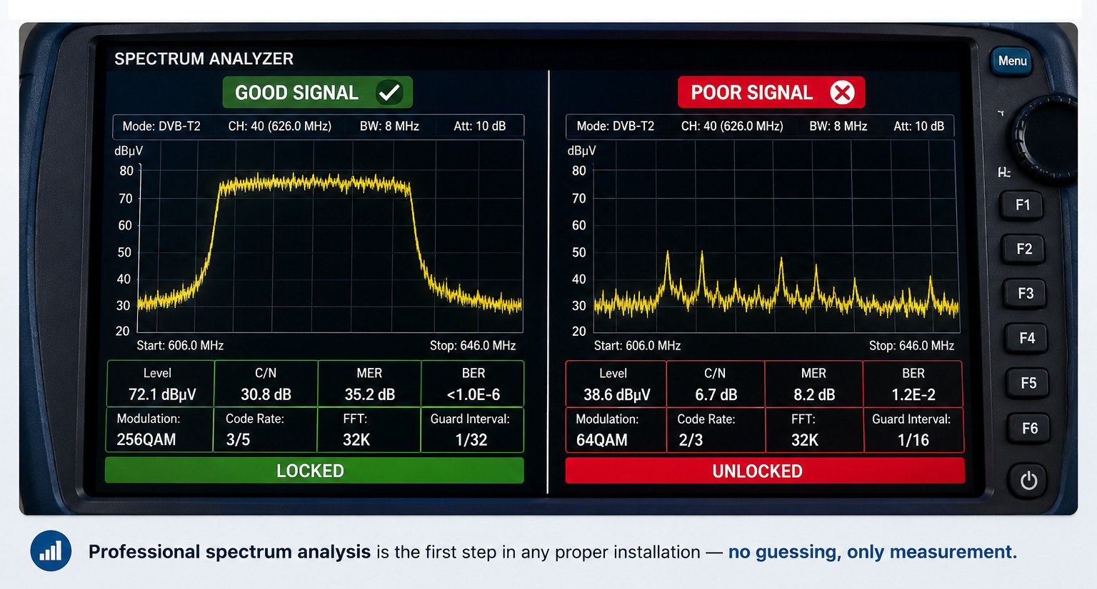
1.1. Antenna Modifications and Classification
Understanding antenna types is essential for matching the right hardware to the right environment:
| Type | Best For | Key Characteristics |
|---|---|---|
| Yagi-Uda | Rural/distant transmitters | High gain, narrow beamwidth |
| Log-Periodic | Urban/reflected signals | Broadband, moderate gain |
| Panel (Flat) | Aesthetic indoor use | Low profile, limited gain |
| Active | Weak signal areas | Built-in amplifier, requires power |
Band Considerations:
- Russia DVB-T2: UHF 470–862 MHz (channels 21–69)
- Greece Digea: UHF Band IV/V (470–862 MHz)
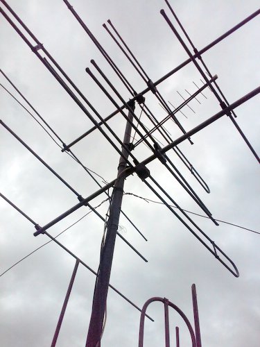
Selecting the correct antenna type — Yagi for distance, Log-periodic for multipath environments.
1.2. The Signal Transport Problem
The Physics: Signal loss in coaxial cable is frequency-dependent and length-dependent. At 800 MHz, a typical RG-6 cable loses approximately 20 dB per 100 meters. This means:
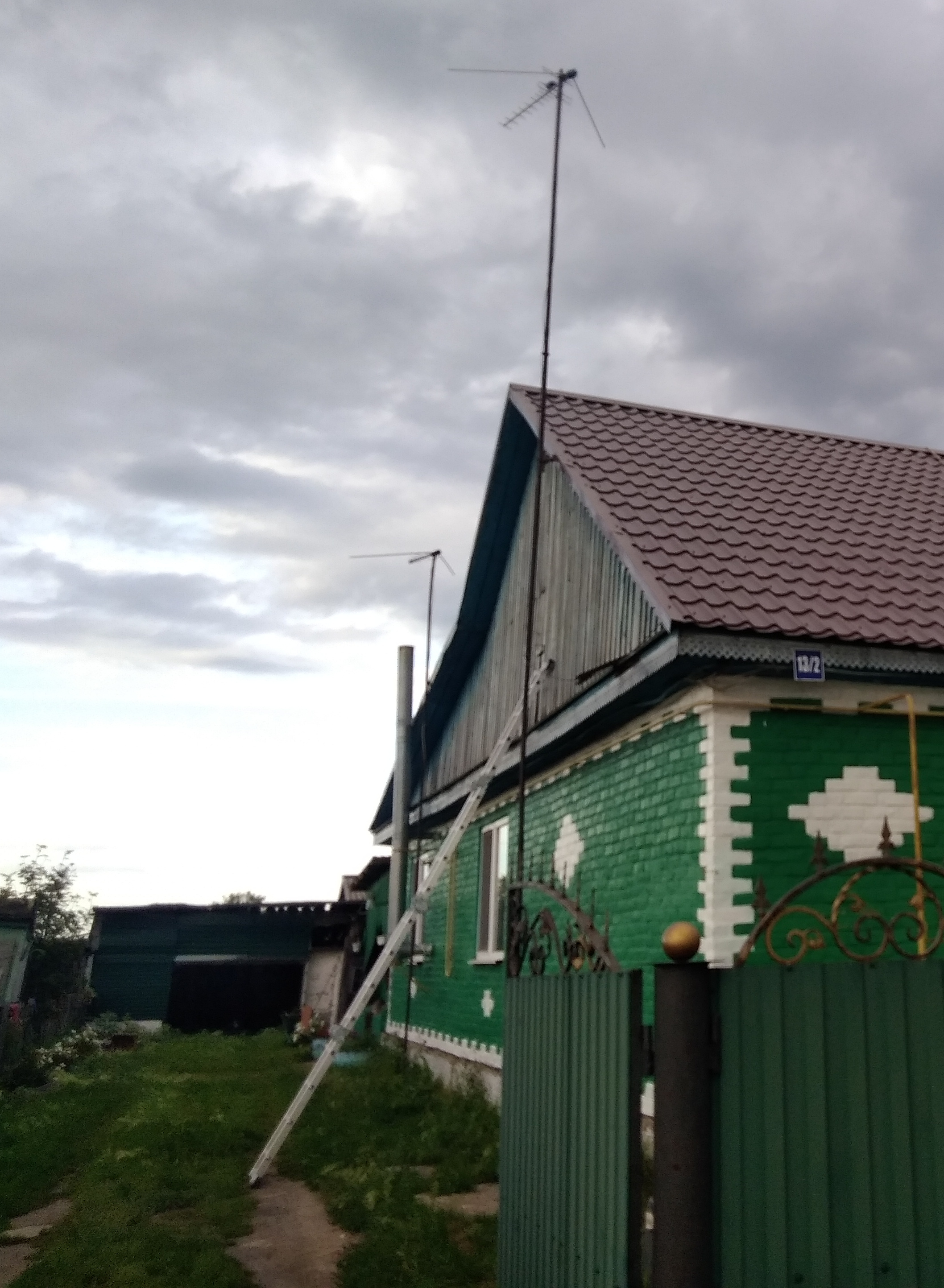
How cable length and quality affect signal strength — a critical factor often overlooked.
Antenna output:     70 dBµV
Cable loss (30m):   -6 dB
Signal at TV:       64 dBµV (acceptable)
Cable loss (50m):  -10 dB
Signal at TV:       60 dBµV (marginal)
Cable loss (80m):  -16 dB
Signal at TV:       54 dBµV (failure)
This is why we see so many “weak signal” complaints — the cable is simply too long and too lossy.
1.3. The Golden Rule: Amplifier Placement
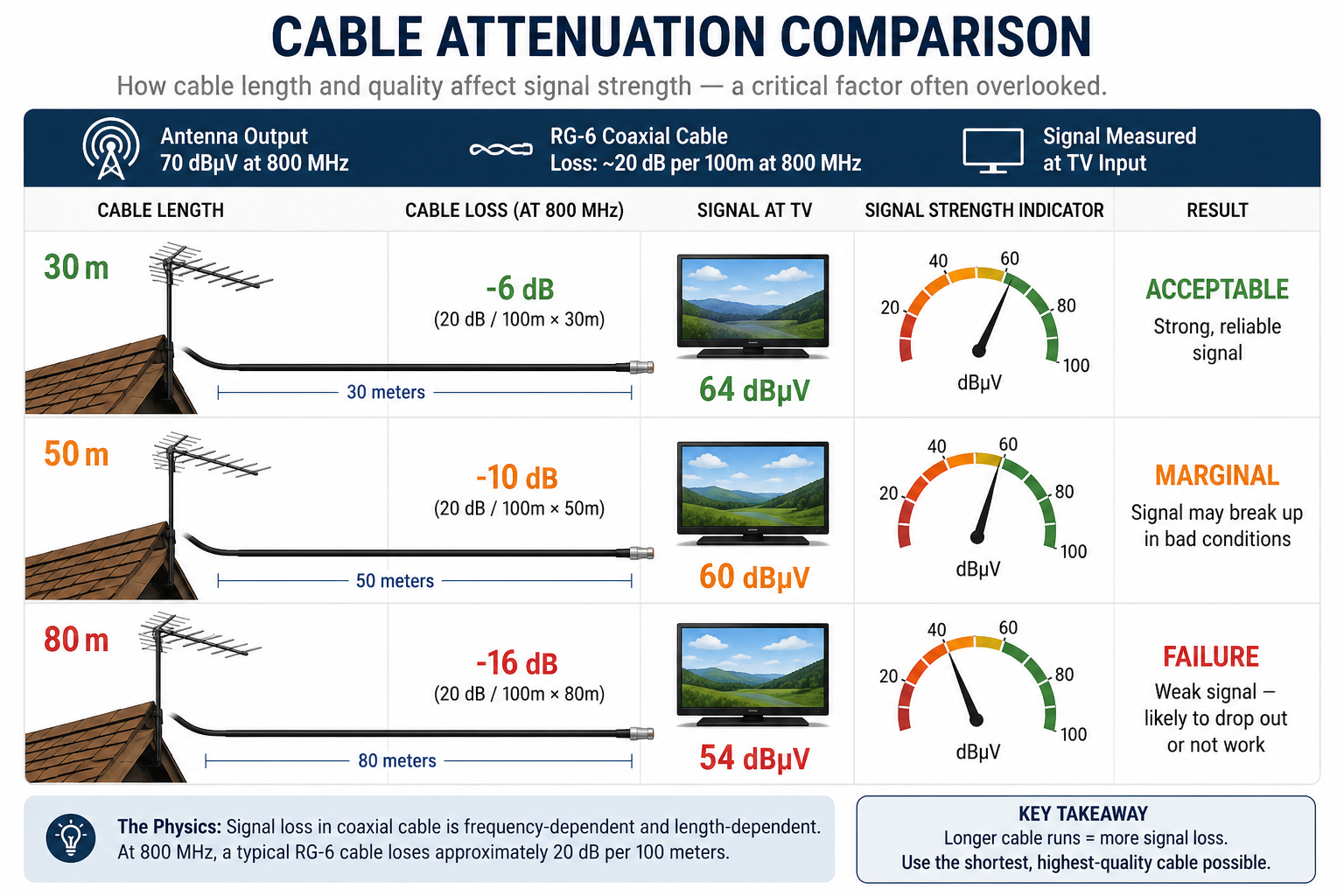
The single most common mistake I encounter is placing the amplifier next to the television.
Why this fails:
- The weak signal travels 30+ meters before amplification
- The cable picks up noise along the way
- You amplify both signal AND noise
The Correct Approach:
- Install a mast-head amplifier (LNA — Low Noise Amplifier) within 1.5 meters of the antenna elements
- The amplifier boosts the signal before it enters the long cable
- The power supply remains indoors (safe from weather)
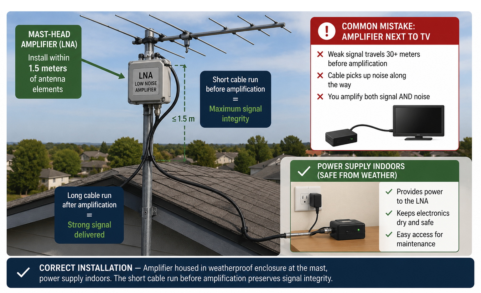
Correct installation — amplifier housed in weatherproof enclosure at the mast, power supply indoors. The short cable run before amplification preserves signal integrity.
1.4. Multiple Consumers: The Distribution Problem
When one antenna serves multiple televisions, signal splitting introduces losses:
| Splitter Type | Loss per Output |
|---|---|
| 2-way | ~3.5 dB |
| 3-way | ~5.5 dB |
| 4-way | ~7.5 dB |
| 8-way | ~11.5 dB |
Solutions I Implement:
- Distribution Amplifiers — compensated splitters that boost signal after splitting
- Taps with Attenuation — for uneven cable runs (shorter runs need less signal)
- Multi-port Mast Amplifiers — multiple outputs directly at the antenna
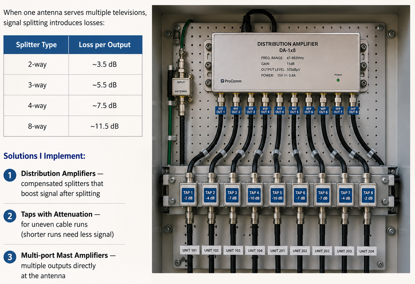
Professional distribution panel for a multi-tenant building — clean, labeled, and properly terminated.
1.5. Coaxial Cable Quality — The Hidden Failure Point
I have seen installations fail because of “just any cable” mentality. Cable quality is not optional.
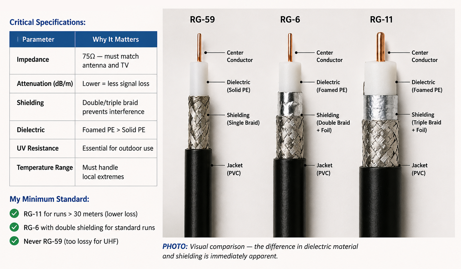
Critical Specifications:
| Parameter | Why It Matters |
|---|---|
| Impedance | 75Ω — must match antenna and TV |
| Attenuation (dB/m) | Lower = less signal loss |
| Shielding | Double/triple braid prevents interference |
| Dielectric | Foamed PE > Solid PE |
| UV Resistance | Essential for outdoor use |
| Temperature Range | Must handle local extremes |
My Minimum Standard:
- RG-11 for runs > 30 meters (lower loss)
- RG-6 with double shielding for standard runs
- Never RG-59 (too lossy for UHF)
1.6. Analog vs. Digital TV — Understanding the Difference
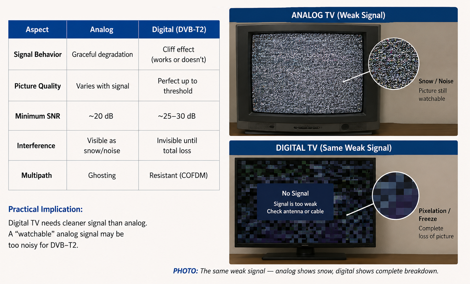
Many clients ask: “Why did my analog TV work but digital doesn’t?”
| Aspect | Analog | Digital (DVB-T2) |
|---|---|---|
| Signal Behavior | Graceful degradation | Cliff effect (works or doesn’t) |
| Picture Quality | Varies with signal | Perfect up to threshold |
| Minimum SNR | ~20 dB | ~25-30 dB |
| Interference | Visible as snow/noise | Invisible until total loss |
| Multipath | Ghosting | Resistant (COFDM) |
Practical Implication: Digital TV needs cleaner signal than analog. A “watchable” analog signal may be too noisy for DVB-T2.
Part 2: Satellite Antennas and Satellite Internet
The Core Challenge
Satellite systems are the only option for many remote locations. In Greece, they serve thousands of island residents; in Russia, they reach the most remote Siberian villages.
2.1. Satellite Antenna Types
| Type | Application | Pros | Cons |
|---|---|---|---|
| Offset (Off-set) | Home Ku-band | Low wind load, sheds rain/snow | Requires precise alignment |
| Prime-Focus | C-band, professional | High efficiency | Large, heavy, high wind load |
| Mesh | High-wind areas | Low wind resistance | Slightly lower gain |
| Motorized | Multi-satellite reception | Access to all satellites | Complex, expensive |
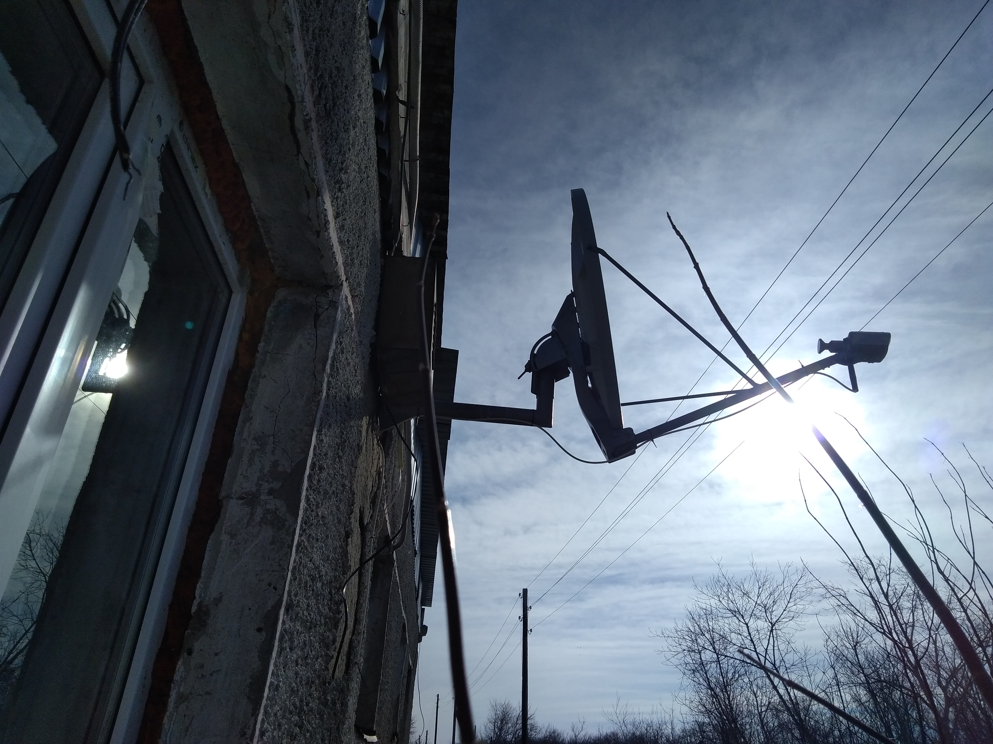
Offset dish
2.2. Converters (LNBs) — Circular vs. Linear Polarization
The LNB (Low Noise Block converter) is the critical component that receives and downconverts the satellite signal.
| Polarization | Use Case | Advantage |
|---|---|---|
| Linear (H/V) | Most European satellites | Standard, widely available |
| Circular (L/R) | Some North American, military | More tolerant of alignment error |
Practical Note: In Greece, Cosmote TV (Eutelsat 9°E) and Hellas Sat (39°E) use linear polarization. I always verify the specific transponder requirements before specifying an LNB.
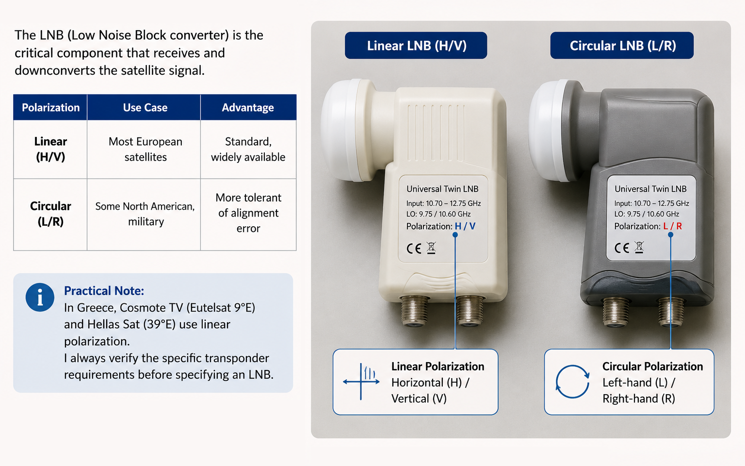
Understanding LNB polarization markings is essential for correct selection.
2.3. Multi-Satellite Systems
When clients need channels from multiple satellites (e.g., Cosmote TV at 9°E + Hot Bird at 13°E + Hellas Sat at 39°E):
My Solutions:
-
Multifeed System — Multiple LNBs on a single dish
- Advantages: Single dish, single cable run
- Limitation: Satellite positions must be within ~20° of each other
-
DiSEqC Switches — Electronic switching between LNBs
- DiSEqC 1.0: Up to 4 inputs
- DiSEqC 1.1: Up to 16 inputs
- The receiver sends a command to select the correct LNB
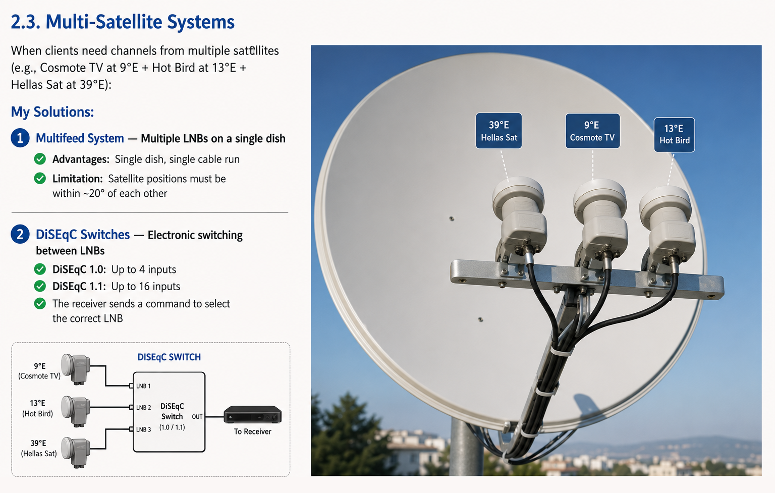
Professional multifeed installation — three LNBs, one dish, seamless switching.
2.4. Satellite Lifecycle and Orbital Changes
What clients don’t realize:
- Satellites have a finite life (typically 10-15 years)
- They consume fuel to maintain their orbital position
- At end-of-life, they move to a “graveyard orbit” and are replaced
Why this matters:
- Replacement satellites may have different transponder frequencies
- Your dish may need realignment
- Your LNB may need replacement
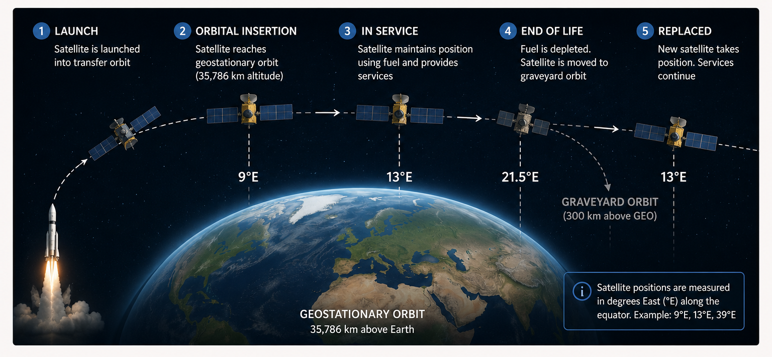
The life cycle of a geostationary satellite — from launch to graveyard.
2.5. Satellite Internet — Two Directions
| Type | Example | Latency | Best For |
|---|---|---|---|
| GEO (Geostationary) | Traditional satellite internet | 500-700 ms | Remote areas, backup links |
| LEO (Low Earth Orbit) | Starlink, OneWeb | 20-50 ms | Streaming, gaming, VPN |
My Experience:
- Installed both GEO and Starlink systems
- In Greece, Starlink has over 60,000 subscribers (as of 2026)
- Professional mounting and integration is essential — I handle the entire process
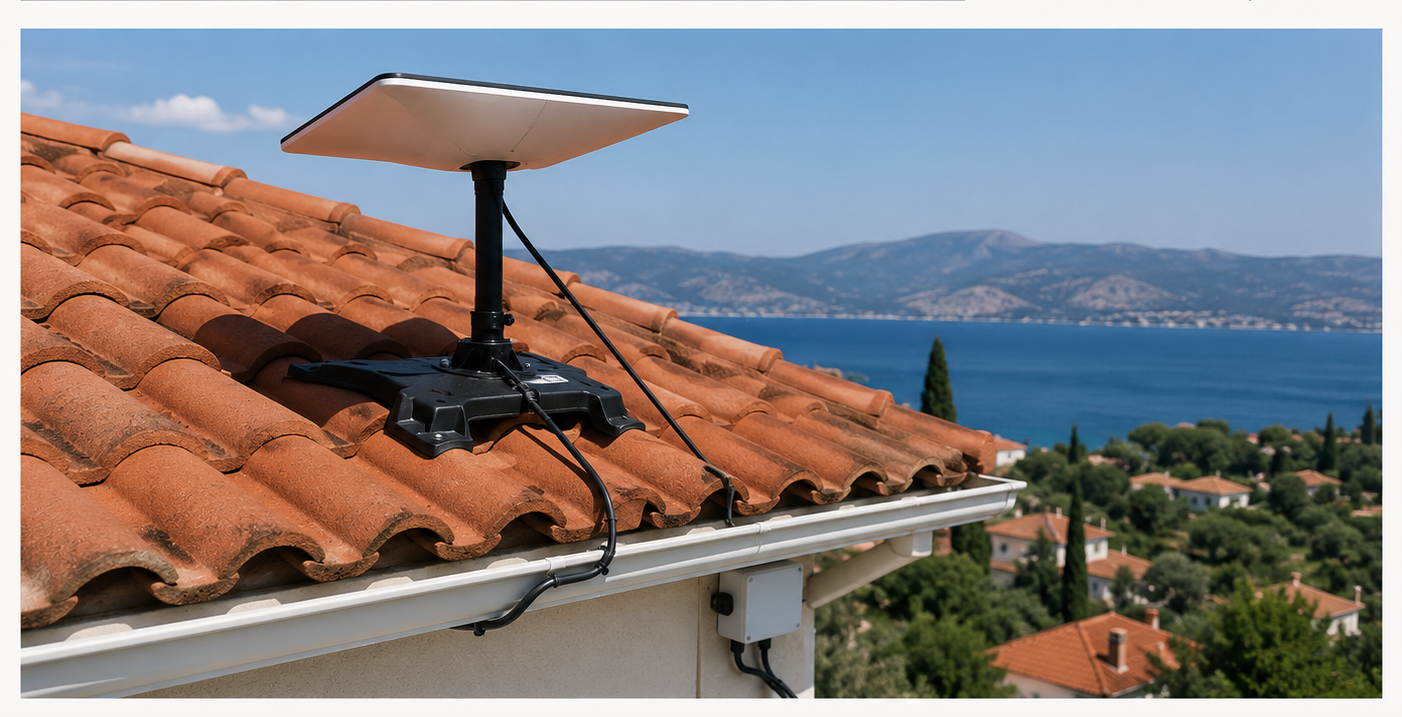
My Starlink installation — non-penetrating roof mount, clean cable routing, weatherproof connections.
Part 3: Cellular and Wi-Fi Antennas
The Core Challenge
“The signal is perfect on the roof but zero inside.” This is the most common complaint I hear.
3.1. Device Types
| Type | Description | Best For |
|---|---|---|
| Built-in Antenna | Integrated into router | Convenience, weak performance |
| External Antenna + Modem | Separate components | Maximum performance |
| All-in-One | Antenna + modem in weatherproof case | Outdoor installations |
My Recommendation: I strongly prefer External Antenna + Internal Modem for maximum flexibility and performance.
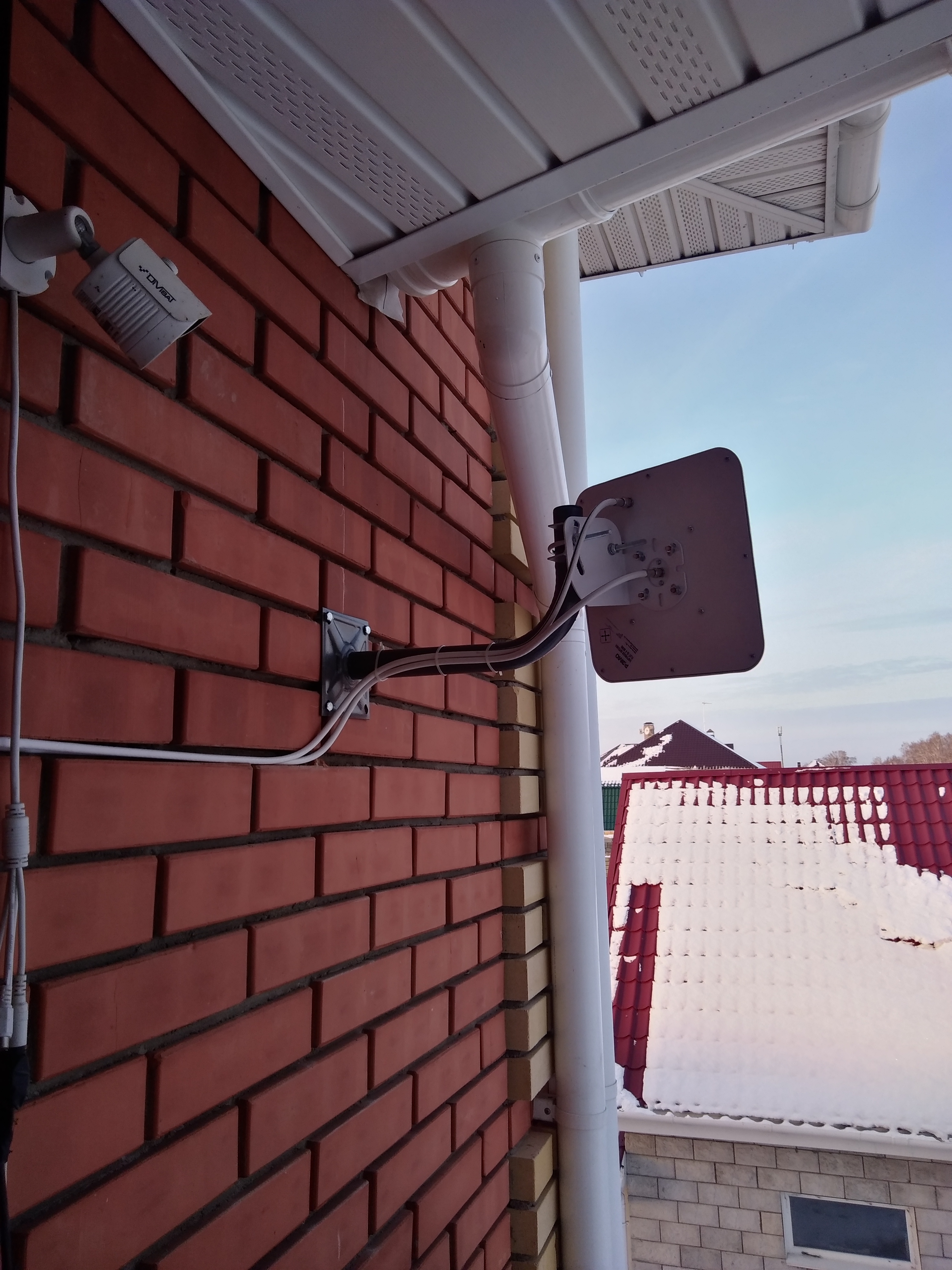
My standard external antenna installation — high-gain directional panel mounted on roof/wall with minimal cable run.
3.2. The Antenna-Modem Problem
The Issue: Every meter of cable between the external antenna and the internal modem introduces loss. At 2600 MHz, this loss can be 5-10 dB over 10 meters.
My Solutions:
- Use Low-Loss Cable (LMR-400 or equivalent)
- Minimize Cable Length — mount the router as close to the antenna as practical
- Active Antennas — built-in amplifier compensates for cable loss
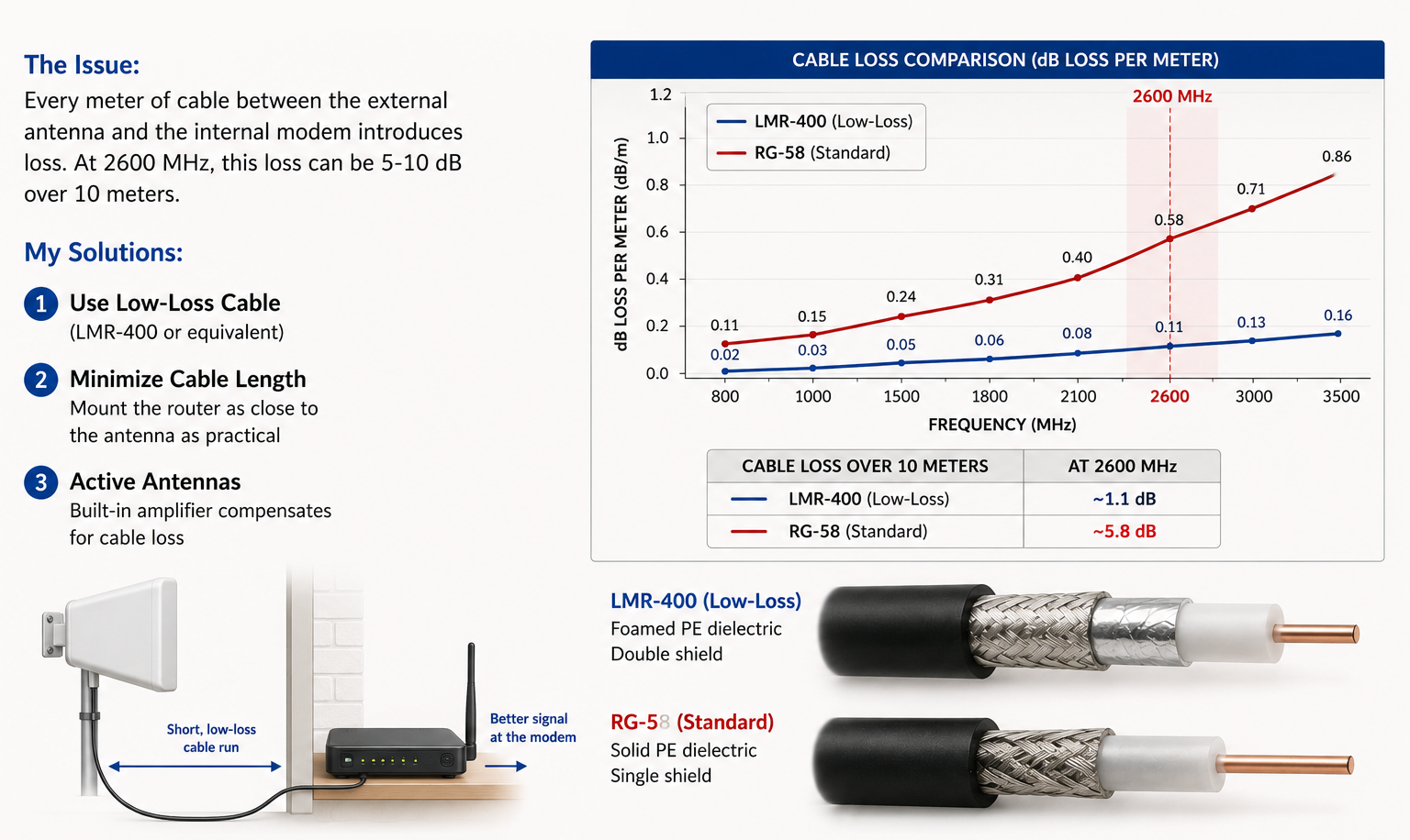
LMR-400 vs. RG-58 at cellular frequencies — the difference is significant.
3.3. Cellular Bands — Matching Antenna to Operator
Understanding the frequency bands used by each operator is essential for correct antenna selection.
| Band | Frequency | Use Case | Advantage | Disadvantage |
|---|---|---|---|---|
| B20 (800 MHz) | Low | Rural coverage | Excellent range | Lower capacity |
| B8 (900 MHz) | Low | Legacy GSM | Good penetration | Slower speeds |
| B3 (1800 MHz) | Medium | Urban coverage | Good balance | Moderate range |
| B7 (2600 MHz) | High | Dense urban | High speed | Short range |
| n28 (700 MHz) | Low (5G) | New 5G coverage | Excellent coverage | Limited deployment |
| n78 (3500 MHz) | High (5G) | 5G capacity | Very high speed | Poor penetration |
My Approach:
- Ask: “Which operator do you use?” (Cosmote, Vodafone, Nova in Greece)
- Map the frequencies deployed at the client’s location
- Select an antenna optimized for those specific bands
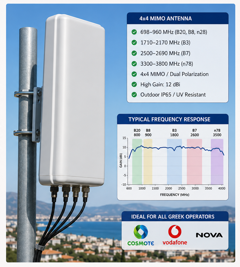
Professional-grade 4x4 MIMO antenna covering all Greek cellular bands.
3.4. Long-Distance Wi-Fi — Overcoming Obstacles
The Physics:
- 2.4 GHz and 5 GHz signals are easily blocked by trees, buildings, and terrain
- Line-of-sight is critical for reliable links over 100+ meters
My Solutions:
- Directional Antennas (Yagi, Parabolic, Panel) — focus signal in one direction
- Frequency Selection — 5 GHz has more bandwidth and less congestion than 2.4 GHz
- Height — elevate antennas to clear the Fresnel zone (the ellipsoidal region of space that must be clear for optimal signal)
Rule of Thumb: For a 1 km link, the Fresnel zone radius is approximately 3 meters. If there are trees or buildings in this zone, the link will fail.
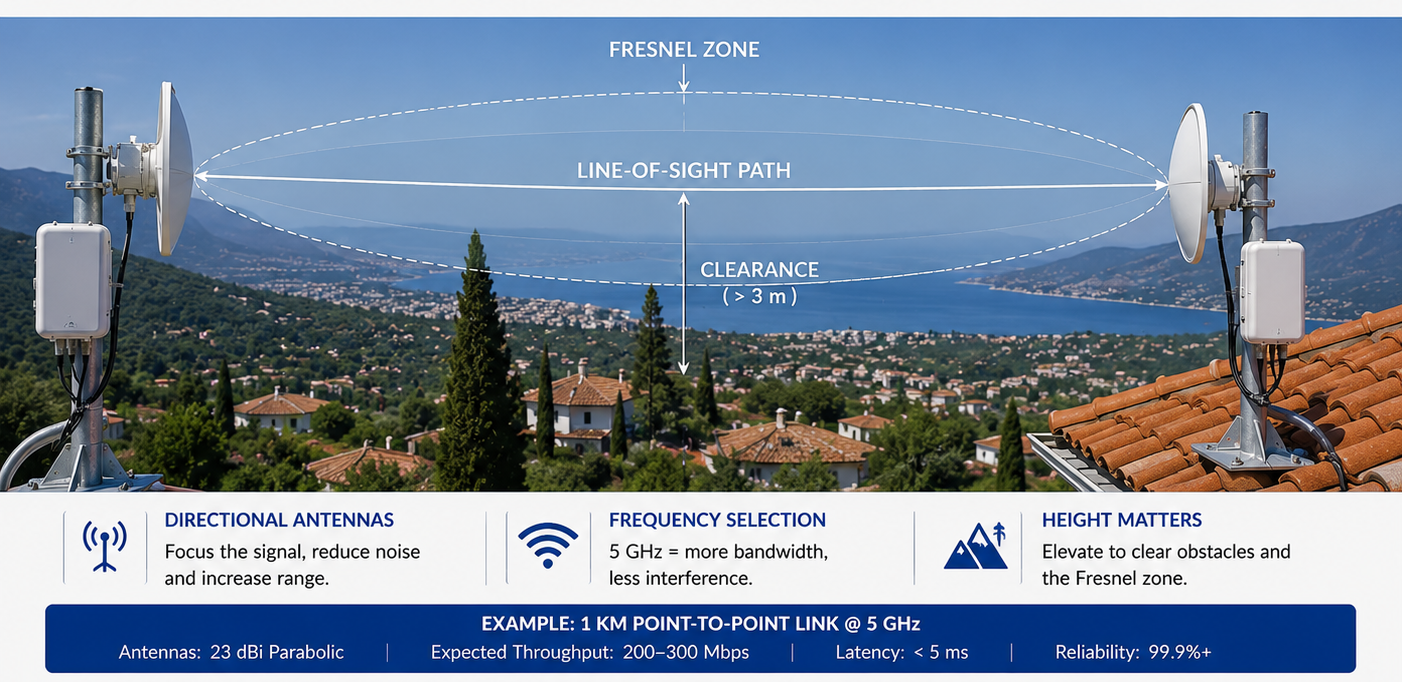
Professional point-to-point installation — clear line-of-sight, proper Fresnel zone clearance, and premium directional antennas.
3.5. Cellular Amplifiers (Repeaters/Boosters)
The Problem: Amplifiers are often installed incorrectly, causing:
- Self-oscillation (feedback loop)
- Network interference (affecting other users)
- No improvement in actual data speed
My Installation Methodology:
- Measure Base Station Location — point the donor antenna precisely at the nearest tower
- Ensure Isolation — maintain >20 dB separation between external and internal antennas
- Set Gain Appropriately — too much gain causes oscillation, too little is useless
- ALC (Automatic Level Control) — prevents overload from strong signals
Correct repeater installation — donor antenna on roof pointed at tower, internal antenna in building with adequate separation.
3.6. Operator Differences — Standards and Compatibility
In Russia, I worked with Megafon, MTS, Beeline, and Tele2 — each with slightly different frequency allocations.
In Greece, I am prepared to work with:
- Cosmote — GSM 900/1800, UMTS, LTE B3/B7/B20, 5G n28/n1/n78
- Vodafone — similar spectrum holdings
- Nova (formerly Wind) — similar spectrum holdings
The Key: Not all amplifiers support all operators. I specify amplifiers that cover the exact bands used by the client’s operator.
Part 4: Video Surveillance (DVR/CCTV)
The Core Challenge
Clients often buy cameras without understanding the cabling and distance limitations, leading to unreliable systems.
4.1. Camera Types — HD vs. IP
| Parameter | HD (Analog) | IP (Digital) |
|---|---|---|
| Resolution | Up to 4K | Up to 4K+ |
| Cable | Coaxial (RG-59/RG-6) | UTP (CAT5e/CAT6) |
| Max Distance | 300-500 m | 100 m (without repeaters) |
| Power | Separate or over coax | PoE (Power over Ethernet) |
| Cost | Lower | Higher |
| Scalability | Each camera needs dedicated cable | Switches allow multiple cameras |
| Latency | Lower | Slightly higher |
My Recommendation:
- HD-TVI for runs > 100 meters (up to 500 m possible)
- IP for runs < 100 meters with PoE simplicity
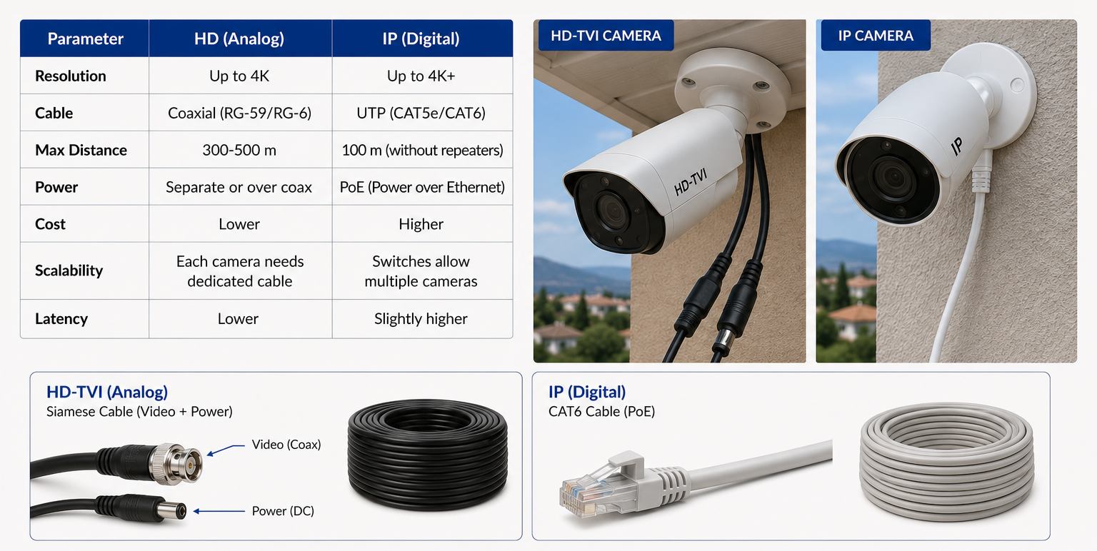
Two camera types — HD-TVI with Siamese cable for long runs, IP with CAT6 for PoE convenience.
4.2. Cable Types and Maximum Distances
| Cable Type | Max Distance | Best For |
|---|---|---|
| RG-59/U | 200 m | Short-to-medium runs |
| RG-6/U | 400-500 m | Long runs |
| CAT5e/CAT6 | 100 m (Ethernet) | IP cameras |
| CAT6 with Active Balun | 300 m | Extending IP cameras |
Important: Voltage drop limits power delivery over long cables. For HD-TVI cameras running on 12V DC, I use thicker gauge cables or inject power at both ends for long runs.
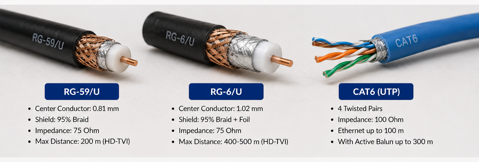
Choosing the right cable for the right distance — the physical difference is significant.
4.3. Hybrid Systems — The Best of Both Worlds
In large properties, I design hybrid systems:
- IP cameras near the NVR (within 100 m) using CAT6
- HD-TVI cameras for distant locations using RG-6 coax
- Hybrid DVR/NVR that supports both camera types
This gives clients the best performance at the lowest cost, without artificial limitations.
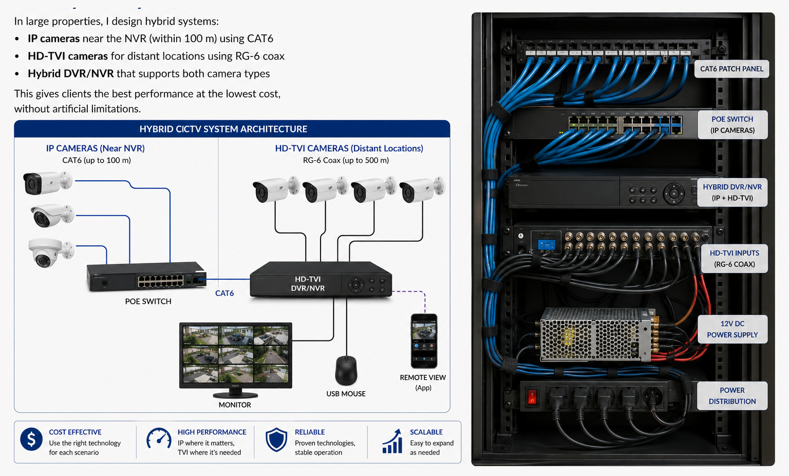
My hybrid system installation — clean, organized, and scalable.
Part 5: Regulatory Compliance — From Russia to Europe
The Silent Challenge
In Russia, I navigated the complex GOST standards and Roskomnadzor licensing requirements. This experience has prepared me for European regulations.
For Greece (My Research):
- EETT (Hellenic Telecommunications and Post Commission) — the licensing authority
- Law 4635/2019 — regulates antenna constructions
- Law 4067/2012 — building height and placement regulations
- SILIA — the electronic application system for antenna licenses (via gov.gr)
- EMF Limits — strict public safety exposure limits
My Commitment: Every installation I perform is fully compliant, licensed (where required), and safe. I handle the paperwork so the client doesn’t have to worry.